
Latest Post

What is Industry 4.0?

  What is Industry 4.0 and what are some of the technologies that are driving it? Industry 4.0 is a term that refers to the fourth industrial revolution, which is characterized by the integration of digital technologies, such as artificial intelligence, cloud computing, big data, the internet of things, robotics, and 3D printing, into the manufacturing sector. Industry 4.0 aims to create smart factories that are more efficient, flexible, and responsive to customer needs and market changes. Some of the technologies that are enabling Industry 4.0 are: - Artificial intelligence (AI) : AI is the ability of machines to perform tasks that normally require human intelligence, such as reasoning, learning, decision-making, and problem-solving. AI can help optimize production processes, improve product quality, reduce costs, and enhance customer satisfaction. - Cloud computing: Cloud computing is delivering computing services, such as servers, storage, databases, software, and analytics, over t

What is IoT?

As the author of this blog page, I'd like to take a deeper dive into the concept of the Internet of Things (IoT).

The IoT refers to the network of physical objects, devices, and appliances that are embedded with sensors, software, and network connectivity, allowing them to collect and exchange data. This data can be used to automate processes, improve efficiency, and make our lives easier and more convenient.


One of the key benefits of the IoT is its ability to allow devices to communicate and share data with each other and with a central server or cloud platform. This enables a wide range of applications, including home automation, smart cities, industrial control systems, and health monitoring.

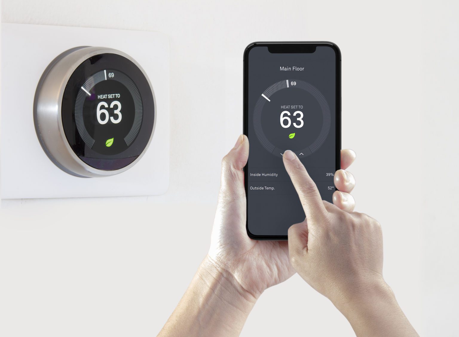
For example, a smart thermostat can be programmed to adjust the temperature in a home based on the preferences of the occupants and the weather outside. It can also be controlled remotely through a smartphone app, allowing users to make adjustments from anywhere.


Connected cars are another example of the IoT in action. These vehicles can transmit data about their location, speed, and fuel efficiency to the manufacturer or a central server. This data can be used to improve the performance of the car and alert the manufacturer to any potential issues that need to be addressed.

In the workplace, IoT devices can be used to track the movement and location of employees, as well as monitor the performance of equipment and machinery. Smart cities can use sensors and other IoT technologies to improve traffic flow, reduce energy consumption, and enhance public safety.


However, the IoT also raises concerns about privacy and security. As more devices are connected to the internet, there is a risk that sensitive data may be vulnerable to hackers or other malicious actors. It's important for individuals and organizations to take steps to protect their data and ensure the security of their IoT devices.

In conclusion, the IoT is an exciting and rapidly evolving field with the potential to transform the way we live and work. As more devices and appliances become connected, we can expect to see a wide range of new applications and innovations that will make our lives easier and more convenient.

Comments

Popular

Playing with Buttons

Button Pushbuttons or switches connect two points in a circuit when you press them. This example turns on the built-in LED on pin 13 when you press the button. Hardware Arduino Board Momentary button or Switch 10K ohm resistor hook-up wires breadboard Circuit diagram Code // constants won't change. They're used here to // set pin numbers: const int buttonPin = 2 ;     // the number of the pushbutton pin const int ledPin =   13 ;      // the number of the LED pin // variables will change: int buttonState = 0 ;         // variable for reading the pushbutton status void setup () {   Serial . begin ( 9600 );   // initialize the LED pin as an output:   pinMode (ledPin, OUTPUT);   // initialize the pushbutton pin as an input:   pinMode (buttonPin, INPUT); } void loop () {   // read the state of the pushbutton value:   buttonState = digitalRead (buttonPin);   // Show the state of pushbutton on serial monitor   Serial . println (buttonState);   // check if the pushbutton is p

Turn LED On and Off Through LDR

  LDR An LDR ( Light Dependent Resistor ) is a component that has a (variable) resistance that changes with the light intensity that falls upon it. This allows them to be used in light sensing circuits. A photoresistor is made of a high resistance semiconductor. Hardware Required Arduino Board LED 220 ohm resistor LDR 10k ohms resistor Circuit Diagram Code int ldr=A0; //Set A0(Analog Input) for LDR. int value= 0 ; void setup () { Serial . begin ( 9600 ); pinMode ( 3 ,OUTPUT); } void loop () { value= analogRead (ldr); //Reads the Value of LDR(light). Serial . println ( "LDR value is :" ); //Prints the value of LDR to Serial Monitor. Serial . println (value); if (value< 300 )   {     digitalWrite ( 3 ,HIGH); //Makes the LED glow in Dark.   }   else   {     digitalWrite ( 3 ,LOW); //Turns the LED OFF in Light.   } }

Home Automation

A smart system made by using Node MCU dev board. What is Node MCU? NodeMCU is an open-source firmware for which open-source prototyping board designs are available. The name "NodeMCU" combines "node" and "MCU" (micro-controller unit). The term "NodeMCU" strictly speaking refers to the firmware rather than the associated development kits.  Both the firmware and prototyping board designs are open source. Requirments Node MCU 4 channel relay toggle switch * 4 Hi-links (220v ac to 5v dc) Circuit Diagram Program #ifdef ENABLE_DEBUG         #define DEBUG_ESP_PORT Serial         #define NODEBUG_WEBSOCKETS         #define NDEBUG #endif #include <Arduino.h> #include <ESP8266WiFi.h> #include "SinricPro.h" #include "SinricProSwitch.h" #include <map> #define WIFI_SSID         "your wifi name"     #define WIFI_PASS         "your wifi pass" #define APP_KEY           "this code is prov

MQ2 Gas Sensor

 About Gas Sensor The MQ series of gas sensors use a small heater inside with an electrochemical sensor. They are sensitive to a range of gasses and are used indoors at room temperature. The output is an analog signal and can be read with an analog input of the Arduino. The MQ-2 Gas Sensor module is useful for gas leakage detection in homes and industries. It can detect LPG, i-butane, propane, methane, alcohol, hydrogen, and smoke. Some modules have a built-in variable resistor to adjust the sensitivity of the sensor. Note:  The sensor becomes very hot after a while, don't touch it! Required  Arduino UNO Breadboard MQ-2 Gas sensor module Red, Green led 5mm 220 Ohm Buzzer The connections are pretty easy: The MQ-5 sensor Pin-> Wiring to Arduino Uno A0-> Analog pins D0-> none GND-> GND VCC-> 5V other components Pin-> Wiring to Arduino Uno D13-> +ve of buzzer GND-> -ve of buzzer D12-> anode of red light D11-> anode of green light GND-> cathode of red li

Temperature sensor

About the LM35 The LM35 is an inexpensive, precision Centigrade temperature sensor made by  Texas Instruments . It provides an output voltage that is linearly proportional to the Centigrade temperature and is, therefore, very easy to use with the Arduino. The sensor does not require any external calibration or trimming to provide accuracies of ±0.5°C at room temperature and ±1°C over the −50°C to +155°C temperature range. One of the downsides of the sensor is that it requires a negative bias voltage to read negative temperatures. So if that is needed for your project, I recommend using the DS18B20 or TMP36 instead. The TMP36 by Analog Devices is very similar to the LM35 and can read temperatures from -40°C to 125°C without any external components Note that the sensor operates on a voltage range of 4 to 30 V and that the output voltage is independent of the supply voltage. The LM35 is part of a series of analog temperature sensors sold by Texas Instruments. Other members of the series i

Mini Oscilloscope via Arduino Nano

What is an oscilloscope?   An  oscilloscope , formerly known as an oscillograph, is an instrument that graphically displays electrical signals and shows how those signals change over time. It measures these signals by connecting with a sensor, which is a device that creates an electrical signal in response to physical stimuli like sound, light, and heat. For instance, a microphone is a sensor that converts sound into an electrical signal. Oscilloscopes are often used when designing, manufacturing, or repairing electronic equipment. Engineers use an oscilloscope to measure electrical phenomena and solve measurement challenges quickly and accurately to verify their designs or confirm that a sensor is working properly. Scientists, engineers, physicists, repair technicians, and educators use oscilloscopes to see signals change over time. An automotive engineer might use an oscilloscope to correlate analog data from sensors with serial data from the engine control unit. Meanwhile, a medical

Seven Segment Display Interfacing with Arduino

Seven-Segment Introduction  Let’s start the main part of this tutorial by answering a question: what is a seven-segment display? As its name suggests, a 7-segment device consists of 7  light-emitting diodes . These light-emitting diodes are arranged and packed inside a single display with a specific pattern in mind. If this pattern is controlled in a specific way by turning on and turning off LEDs, a seven-segment device will display a unique number. There is also an extra eighth LED on a seven-segment display which is used to display dots. This dot is sometimes used as a decimal point when we want to display a fractional value.  The picture below shows a seven-segment display and its pinout. The string of eight LEDs on the left side shows the internal connection and a picture on the right side shows how these LEDs are arranged to make a seven-segment display. Pin3 and 8 are common pins. These pins are used to provide either 5 volts or ground in common-anode and common cathode type dis

Play a melody with a Piezo speaker

  Play a Melody using the tone() function This example shows how to use the  tone()  command to generate notes. It plays a little melody you may have heard before. Hardware Required Arduino board piezo buzzer or a speaker hook-up wires Making header file To make the pitches.h file, either click on the button just below the serial monitor icon and choose "New Tab", or use Ctrl+Shift+N. Then paste in the following code: /************************************************* * Public Constants *************************************************/ # define NOTE_B0 31 # define NOTE_C1 33 # define NOTE_CS1 35 # define NOTE_D1 37 # define NOTE_DS1 39 # define NOTE_E1 41 # define NOTE_F1 44 # define NOTE_FS1 46 # define NOTE_G1 49 # define NOTE_GS1 52 # define NOTE_A1 55 # define NOTE_AS1 58 # define NOTE_B1 62 # define NOTE_C2 65 # define NOTE_CS2 69 # define NOTE_D2 73 # define NOTE_DS2 78 # define NOTE_E2 82 # define NOTE_F2 87 # de

Fade an LED

  Fade This example demonstrates the use of the  analogWrite()  function in fading an LED off and on. AnalogWrite uses  pulse width modulation (PWM) , turning a digital pin on and off very quickly with different ratio between on and off, to create a fading effect. Hardware Required Arduino board LED 220 ohm resistor hook-up wires Circuit Diagram Code int led = 9 ;           // the PWM pin the LED is attached to int brightness = 0 ;    // how bright the LED is int fadeAmount = 5 ;    // how many points to fade the LED by // the setup routine runs once when you press reset: void setup () {   // declare pin 9 to be an output:   pinMode (led, OUTPUT); } // the loop routine runs over and over again forever: void loop () {   // set the brightness of pin 9:   analogWrite (led, brightness);   // change the brightness for next time through the loop:   brightness = brightness + fadeAmount;   // reverse the direction of the fading at the ends of the fade:   if (brightness <= 0 || bri

Blinking LED with Arduino UNO

  Blink This example shows the simplest thing you can do with an Arduino to see physical output: it blinks the on-board LED. Hardware Required Arduino Board LED 220 ohm resistor Circuit diagram Code int ledPin= 13 ; //definition digital 13 pins as pin to control the LED void setup () {     pinMode (ledPin,OUTPUT);    //Set the digital 8 port mode, OUTPUT: Output mode } void loop () {       digitalWrite (ledPin,HIGH); //HIGH is set to about 5V PIN8     delay ( 1000 );               //Set the delay time, 1000 = 1S     digitalWrite (ledPin,LOW);  //LOW is set to about 5V PIN8     delay ( 1000 );               //Set the delay time, 1000 = 1S }