Seven-Segment Introduction
Let’s start the main part of this tutorial by answering a question: what is a seven-segment display? As its name suggests, a 7-segment device consists of 7 light-emitting diodes. These light-emitting diodes are arranged and packed inside a single display with a specific pattern in mind. If this pattern is controlled in a specific way by turning on and turning off LEDs, a seven-segment device will display a unique number. There is also an extra eighth LED on a seven-segment display which is used to display dots. This dot is sometimes used as a decimal point when we want to display a fractional value.
The picture below shows a seven-segment display and its pinout. The string of eight LEDs on the left side shows the internal connection and a picture on the right side shows how these LEDs are arranged to make a seven-segment display. Pin3 and 8 are common pins. These pins are used to provide either 5 volts or ground in common-anode and common cathode type displays respectively.
Types of Seven Segment Displays
There are two types of seven-segment displays such as common anode and common cathode.
Common Anode Display
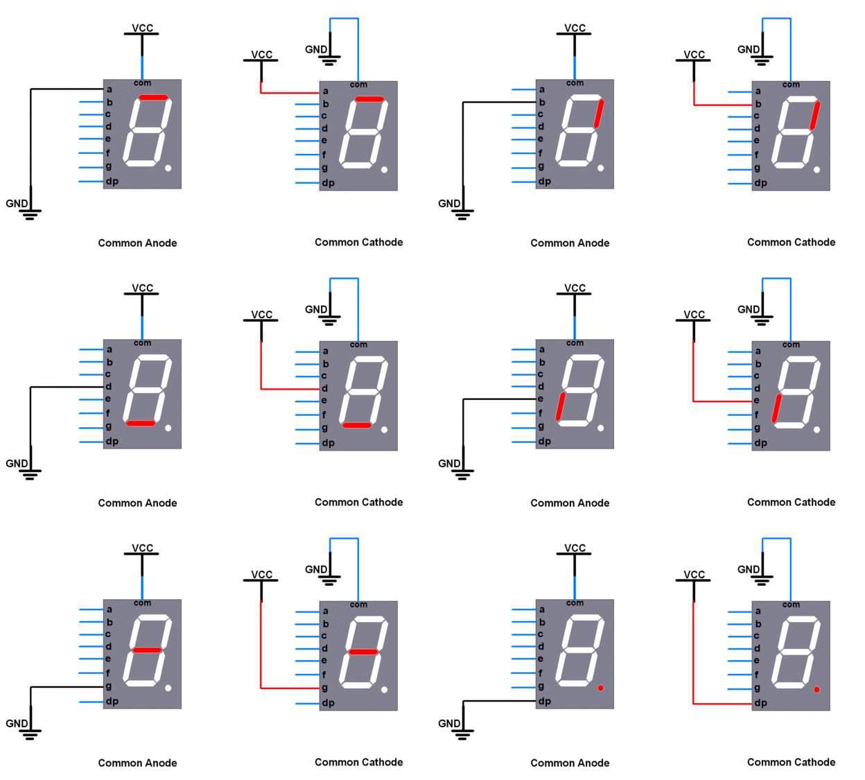
In a common anode display, all the anodes terminals of eight light-emitting diodes are common and connect with a 5-volt power supply. In normal conditions, we apply logic high from Arduino to each segment. Therefore, each segment remains off or does not glow. Similarly, when we want to turn on a specific LED of a seven-segment device, we provide the logic low signal. Because LED glows only when there will be a logic high signal on the anode side and a logic low signal on the cathode side such is the case of a common anode type display.
Common Cathode Display
In a common cathode segment display, all the cathodes of eight light-emitting diodes are common and connect with the ground. To turn off any segment of 7-segment, we apply logic low from Arduino to this segment. Similarly, when we want to turn on a specific LED of a seven-segment device, we provide a logic high signal from an Arduino digital output pin. Because LED glows only when there will be a logic high signal on the anode side and a logic low signal on the cathode side such is the case of a common cathode type display.
7 Segment Display Interfacing with Arduino
So far in this tutorial, we talked about the internal structure, interfacing logic, and how we can write logic signals to control LED segments of a 7-segment device. In this section, we will learn to interface an Arduino development board with a single seven-segment display.
We will need a breadboard, a few connecting wires, 220-ohm resistors, and an Arduino development board. First, connect a 7-segment device to a breadboard and connect a 220ohm resistor with each LED segment except a common terminal.
As you see the pinout of a common anode 7-segment display by facing a dot point towards the upper side, pins 1-5 are on the upper side, and pins 10-6 are on the lower side of the module. Now make the connection according to the schematic diagrams given below.
This table shows the connections of a segment display with Arduino.
| Arduino pins | 7-Segment display pins |
|---|---|
| 5V | 3 or 8 |
| 2 | a |
| 3 | b |
| 4 | c |
| 6 | d |
| 7 | e |
| 8 | f |
| 9 | g |
| 5 | DP |
After you complete the connections, your interfacing diagram will look like these:
Circuit Diagram:
 |
| Common Anode type seven segment display interfacing with Arduino |
 |
| Common Cathode type seven segment display interfacing with Arduino |
Arduino Library
Now let’s write an Arduino code to control a single-digit 7-segment display. There are two ways to write a code. One is using an Arduino library and the other way is to write your own code from scratch. First, we will see an Arduino library method where we will use an Arduino library for a seven-segment display.
.First, click on the button below and download the seven-segment library.
Arduino Code with Library
Now let’s see the example code. This code is a counter that counts from 0-9 by displaying the counter value on 7-segment.
#include "SevSeg.h"SevSeg sevseg;
void setup(){  //define number of seven-segment digits to one  byte sevenSegments = 1;    //variable used to define the number of seven segment and common pins  //but we are using only one 7-segment. Hence leave it empty  byte CommonPins[] = {};
  //array to store arduino pin connections with LED segments in order: A, B, C, D, E, F, G, DP  byte LEDsegmentPins[] = {2, 3, 4, 6, 7, 8, 9, 5};  bool resistorsOnSegments = true;
  //Initialize sevseg object that created above with input arguments defined already  sevseg.begin(COMMON_ANODE, sevenSegments, CommonPins, LEDsegmentPins, resistorsOnSegments);  //uncomment the following line for common cathode type display and comment the above  //sevseg.begin(COMMON_CATHODE, sevenSegments, CommonPins, LEDsegmentPins, resistorsOnSegments);
  sevseg.setBrightness(90);}
void loop(){    //loop display counter values from 0-9   for(int i = 0; i < 10; i++)   {     sevseg.setNumber(i);  // Display counter value     sevseg.refreshDisplay(); // refresh required      delay(1000); // delay of one second   }}
Copy this code to Arduino IDE and try this code the schematic diagram you designed in the last step. You will get counter output on a seven-segment display and the value of the counter will be updated after every one second.


Comments
Post a Comment