
Latest Post

What is Industry 4.0?

  What is Industry 4.0 and what are some of the technologies that are driving it? Industry 4.0 is a term that refers to the fourth industrial revolution, which is characterized by the integration of digital technologies, such as artificial intelligence, cloud computing, big data, the internet of things, robotics, and 3D printing, into the manufacturing sector. Industry 4.0 aims to create smart factories that are more efficient, flexible, and responsive to customer needs and market changes. Some of the technologies that are enabling Industry 4.0 are: - Artificial intelligence (AI) : AI is the ability of machines to perform tasks that normally require human intelligence, such as reasoning, learning, decision-making, and problem-solving. AI can help optimize production processes, improve product quality, reduce costs, and enhance customer satisfaction. - Cloud computing: Cloud computing is delivering computing services, such as servers, storage, databases, software, and analytics, ov...

Read an ADXL3xx accelerometer.

 ADXL3xx Accelerometer

This tutorial shows you how to read from the ADXL3xx series (e.g. ADXL320, ADXL321, ADXL322, ADXL330) accelerometer and receive the values in the serial monitor of the Arduino Software (IDE) or another application that receives data over the serial port.

This tutorial was built using the breakout boards from Sparkfun. The adafruit accelerometer breakout board also works, though it must be wired differently.

The ADXL3xx outputs the acceleration on each axis as an analog voltage between 0 and 5 volts. To read this, all you need is the analogRead() function.

Hardware Required

  • Arduino Board

  • ADXL3xx Accelerometer

Circuit

The accelerometer uses very little current, so it can be plugged into your board and run directly off of the output from the digital output pins. To do this, you'll use three of the analog input pins as digital I/O pins, for power and ground to the accelerometer, and for the self-test pin. You'll use the other three analog inputs to read the accelerometer's analog outputs.


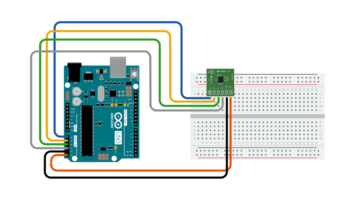
Please, be aware that some accelerometers use 3.3V power supply and might be damaged by 5V. Check the supplier's documentation to find out which is the correct voltage.

Code

The accelerometer connections are defined as constants at the beginning of the sketch, using the two Analog pins 4 and 5 as source of power. This is accomplished using them as Digital I/O pins 18 and 19. If needed, A0 is D14, A1 is D15 and so on.

const int groundpin = 18; const int powerpin = 19;

Setting pin 19 (A5) as HIGH and pin 18 (A4) as LOW provides the 5V with few milliamps needed by the accelerometer to work.

pinMode(groundpin, OUTPUT); pinMode(powerpin, OUTPUT); digitalWrite(groundpin, LOW); digitalWrite(powerpin, HIGH);

This solution allows the breakout boards from Sparkfun to be connected directly to your Arduino board. Different boards may be connected to standard 5V - or 3.3V -and GND pins. In this latter case, the code may be amended commenting the lines above in the void setup() section.

// these constants describe the pins. They won't change:

const int groundpin = 18;             // analog input pin 4 -- ground

const int powerpin = 19;              // analog input pin 5 -- voltage

const int xpin = A3;                  // x-axis of the accelerometer

const int ypin = A2;                  // y-axis

const int zpin = A1;                  // z-axis (only on 3-axis models)

void setup() {

  // initialize the serial communications:

  Serial.begin(9600);

  // Provide ground and power by using the analog inputs as normal digital pins.

  // This makes it possible to directly connect the breakout board to the

  // Arduino. If you use the normal 5V and GND pins on the Arduino,

  // you can remove these lines.

  pinMode(groundpin, OUTPUT);

  pinMode(powerpin, OUTPUT);

  digitalWrite(groundpin, LOW);

  digitalWrite(powerpin, HIGH);
}

void loop() {

  // print the sensor values:

  Serial.print(analogRead(xpin));

  // print a tab between values:

  Serial.print("\t");

  Serial.print(analogRead(ypin));

  // print a tab between values:

  Serial.print("\t");

  Serial.print(analogRead(zpin));

  Serial.println();

  // delay before next reading:

  delay(100);
}

Data

Here are some accelerometer readings collected by positioning the y-axis of an ADXL322 2g accelerometer at various angles from ground. Values should be the same for the other axes, but will vary based on the sensitivity of the device. With the axis horizontal (i.e. parallel to ground or 0°), the accelerometer reading should be around 512, but values at other angles will be different for a different accelerometer (e.g. the ADXL302 5g one).

Angle-90-80-70-60-50-40-30-20-100
Acceleration662660654642628610589563537510
Angle0102030405060708090
Acceleration510485455433408390374363357355

Popular

Playing with Buttons

Button Pushbuttons or switches connect two points in a circuit when you press them. This example turns on the built-in LED on pin 13 when you press the button. Hardware Arduino Board Momentary button or Switch 10K ohm resistor hook-up wires breadboard Circuit diagram Code // constants won't change. They're used here to // set pin numbers: const int buttonPin = 2 ;     // the number of the pushbutton pin const int ledPin =   13 ;      // the number of the LED pin // variables will change: int buttonState = 0 ;         // variable for reading the pushbutton status void setup () {   Serial . begin ( 9600 );   // initialize the LED pin as an output:   pinMode (ledPin, OUTPUT);   // initialize the pushbutton pin as an input:   pinMode (buttonPin, INPUT); } void loop () {   // read the state of the pushbutton value:   buttonState = digitalRead (buttonPin);   // Show the state of pushbutton on s...

Home Automation

A smart system made by using Node MCU dev board. What is Node MCU? NodeMCU is an open-source firmware for which open-source prototyping board designs are available. The name "NodeMCU" combines "node" and "MCU" (micro-controller unit). The term "NodeMCU" strictly speaking refers to the firmware rather than the associated development kits.  Both the firmware and prototyping board designs are open source. Requirments Node MCU 4 channel relay toggle switch * 4 Hi-links (220v ac to 5v dc) Circuit Diagram Program #ifdef ENABLE_DEBUG         #define DEBUG_ESP_PORT Serial         #define NODEBUG_WEBSOCKETS         #define NDEBUG #endif #include <Arduino.h> #include <ESP8266WiFi.h> #include "SinricPro.h" #include "SinricProSwitch.h" #include <map> #define WIFI_SSID         "your wifi name"     #define WIFI_PASS         "your wifi pass" #define APP_KEY...

Turn LED On and Off Through LDR

  LDR An LDR ( Light Dependent Resistor ) is a component that has a (variable) resistance that changes with the light intensity that falls upon it. This allows them to be used in light sensing circuits. A photoresistor is made of a high resistance semiconductor. Hardware Required Arduino Board LED 220 ohm resistor LDR 10k ohms resistor Circuit Diagram Code int ldr=A0; //Set A0(Analog Input) for LDR. int value= 0 ; void setup () { Serial . begin ( 9600 ); pinMode ( 3 ,OUTPUT); } void loop () { value= analogRead (ldr); //Reads the Value of LDR(light). Serial . println ( "LDR value is :" ); //Prints the value of LDR to Serial Monitor. Serial . println (value); if (value< 300 )   {     digitalWrite ( 3 ,HIGH); //Makes the LED glow in Dark.   }   else   {     digitalWrite ( 3 ,LOW); //Turns the LED OFF in Light.   } }

Temperature sensor

About the LM35 The LM35 is an inexpensive, precision Centigrade temperature sensor made by  Texas Instruments . It provides an output voltage that is linearly proportional to the Centigrade temperature and is, therefore, very easy to use with the Arduino. The sensor does not require any external calibration or trimming to provide accuracies of ±0.5°C at room temperature and ±1°C over the −50°C to +155°C temperature range. One of the downsides of the sensor is that it requires a negative bias voltage to read negative temperatures. So if that is needed for your project, I recommend using the DS18B20 or TMP36 instead. The TMP36 by Analog Devices is very similar to the LM35 and can read temperatures from -40°C to 125°C without any external components Note that the sensor operates on a voltage range of 4 to 30 V and that the output voltage is independent of the supply voltage. The LM35 is part of a series of analog temperature sensors sold by Texas Instruments. Other members of the seri...

Mini Oscilloscope via Arduino Nano

What is an oscilloscope?   An  oscilloscope , formerly known as an oscillograph, is an instrument that graphically displays electrical signals and shows how those signals change over time. It measures these signals by connecting with a sensor, which is a device that creates an electrical signal in response to physical stimuli like sound, light, and heat. For instance, a microphone is a sensor that converts sound into an electrical signal. Oscilloscopes are often used when designing, manufacturing, or repairing electronic equipment. Engineers use an oscilloscope to measure electrical phenomena and solve measurement challenges quickly and accurately to verify their designs or confirm that a sensor is working properly. Scientists, engineers, physicists, repair technicians, and educators use oscilloscopes to see signals change over time. An automotive engineer might use an oscilloscope to correlate analog data from sensors with serial data from the engine control unit. Meanwh...

MQ2 Gas Sensor

 About Gas Sensor The MQ series of gas sensors use a small heater inside with an electrochemical sensor. They are sensitive to a range of gasses and are used indoors at room temperature. The output is an analog signal and can be read with an analog input of the Arduino. The MQ-2 Gas Sensor module is useful for gas leakage detection in homes and industries. It can detect LPG, i-butane, propane, methane, alcohol, hydrogen, and smoke. Some modules have a built-in variable resistor to adjust the sensitivity of the sensor. Note:  The sensor becomes very hot after a while, don't touch it! Required  Arduino UNO Breadboard MQ-2 Gas sensor module Red, Green led 5mm 220 Ohm Buzzer The connections are pretty easy: The MQ-5 sensor Pin-> Wiring to Arduino Uno A0-> Analog pins D0-> none GND-> GND VCC-> 5V other components Pin-> Wiring to Arduino Uno D13-> +ve of buzzer GND-> -ve of buzzer D12-> anode of red light D11-> anode of green light GND-> cathode...

Seven Segment Display Interfacing with Arduino

Seven-Segment Introduction  Let’s start the main part of this tutorial by answering a question: what is a seven-segment display? As its name suggests, a 7-segment device consists of 7  light-emitting diodes . These light-emitting diodes are arranged and packed inside a single display with a specific pattern in mind. If this pattern is controlled in a specific way by turning on and turning off LEDs, a seven-segment device will display a unique number. There is also an extra eighth LED on a seven-segment display which is used to display dots. This dot is sometimes used as a decimal point when we want to display a fractional value.  The picture below shows a seven-segment display and its pinout. The string of eight LEDs on the left side shows the internal connection and a picture on the right side shows how these LEDs are arranged to make a seven-segment display. Pin3 and 8 are common pins. These pins are used to provide either 5 volts or ground in common-anode and common ca...

Play a melody with a Piezo speaker

  Play a Melody using the tone() function This example shows how to use the  tone()  command to generate notes. It plays a little melody you may have heard before. Hardware Required Arduino board piezo buzzer or a speaker hook-up wires Making header file To make the pitches.h file, either click on the button just below the serial monitor icon and choose "New Tab", or use Ctrl+Shift+N. Then paste in the following code: /************************************************* * Public Constants *************************************************/ # define NOTE_B0 31 # define NOTE_C1 33 # define NOTE_CS1 35 # define NOTE_D1 37 # define NOTE_DS1 39 # define NOTE_E1 41 # define NOTE_F1 44 # define NOTE_FS1 46 # define NOTE_G1 49 # define NOTE_GS1 52 # define NOTE_A1 55 # define NOTE_AS1 58 # define NOTE_B1 62 # define NOTE_C2 65 # define NOTE_CS2 69 # define NOTE_D2 73 # define NOTE_DS2 78 # define NOTE_E2 82 # define NOTE_F2 87 ...

What is Industry 4.0?

  What is Industry 4.0 and what are some of the technologies that are driving it? Industry 4.0 is a term that refers to the fourth industrial revolution, which is characterized by the integration of digital technologies, such as artificial intelligence, cloud computing, big data, the internet of things, robotics, and 3D printing, into the manufacturing sector. Industry 4.0 aims to create smart factories that are more efficient, flexible, and responsive to customer needs and market changes. Some of the technologies that are enabling Industry 4.0 are: - Artificial intelligence (AI) : AI is the ability of machines to perform tasks that normally require human intelligence, such as reasoning, learning, decision-making, and problem-solving. AI can help optimize production processes, improve product quality, reduce costs, and enhance customer satisfaction. - Cloud computing: Cloud computing is delivering computing services, such as servers, storage, databases, software, and analytics, ov...

Fade an LED

  Fade This example demonstrates the use of the  analogWrite()  function in fading an LED off and on. AnalogWrite uses  pulse width modulation (PWM) , turning a digital pin on and off very quickly with different ratio between on and off, to create a fading effect. Hardware Required Arduino board LED 220 ohm resistor hook-up wires Circuit Diagram Code int led = 9 ;           // the PWM pin the LED is attached to int brightness = 0 ;    // how bright the LED is int fadeAmount = 5 ;    // how many points to fade the LED by // the setup routine runs once when you press reset: void setup () {   // declare pin 9 to be an output:   pinMode (led, OUTPUT); } // the loop routine runs over and over again forever: void loop () {   // set the brightness of pin 9:   analogWrite (led, brightness);   // change the brightness for next time through the loop:   brightness = brightness + fadeAmount; ...