
Latest Post

What is Industry 4.0?

  What is Industry 4.0 and what are some of the technologies that are driving it? Industry 4.0 is a term that refers to the fourth industrial revolution, which is characterized by the integration of digital technologies, such as artificial intelligence, cloud computing, big data, the internet of things, robotics, and 3D printing, into the manufacturing sector. Industry 4.0 aims to create smart factories that are more efficient, flexible, and responsive to customer needs and market changes. Some of the technologies that are enabling Industry 4.0 are: - Artificial intelligence (AI) : AI is the ability of machines to perform tasks that normally require human intelligence, such as reasoning, learning, decision-making, and problem-solving. AI can help optimize production processes, improve product quality, reduce costs, and enhance customer satisfaction. - Cloud computing: Cloud computing is delivering computing services, such as servers, storage, databases, software, and analytics, ov...

Bluetooth Basic

Bluetooth Communication

Bluetooth wireless technology is a short range communications technology intended to replace the cables connecting portable unit and maintaining high levels of security. Bluetooth technology is based on Ad-hoc technology also known as Ad-hoc Pico nets, which is a local area network with a very limited coverage.

COMPONENTS AND SUPPLIES

  1. LED
  2. Arduino uno
  3. 221 ohm resistor
  4. hc-05 bluetooth module
  5. android app given below

Let’s Start Building

The circuit is so simple and small, there are only a few connections to be made

Arduino Pins           Bluetooth Pins

RX (Pin 0)     ———->      TX

TX (Pin 1)      ———->      RX

5V                ———->      VCC

GND             ———->      GND

Connect a LED negative to GND of Arduino and positive to pin 13 with a resistance valued between 220Ω – 1KΩ. And you're done with the circuit


Note: Don’t  Connect RX to RX and TX to TX of Bluetooth to Arduino you will receive no data, Here TX means Transmit and RX means Receive

How Does it Work?

HC 05/06 works on serial communication.here the android app is designed to send serial data to the Bluetooth module when a certain button is pressed. The Bluetooth module at the other end receives the data and sends it to Arduino through the TX pin of the Bluetooth module(RX pin of Arduino). The Code fed to Arduino checks the received data and compares it.If received data is 1 the LED turns on turns OFF when received data is 0

Open the serial monitor and watch the received data

next


How to use the App?

Watch in video how to pair to Bluetooth module

  • Download the Application form here or here
  • Pair your device with HC 05/06 Bluetooth module1) Turn ON HC 05/06 Bluetooth module2) Scan for available device3) Pair to HC 05/06 by entering default password 1234 OR 0000
  • Install  LED application on your android device
  • Open the Application
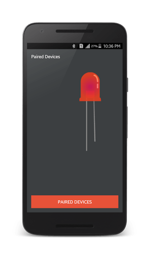
  • Press paired devices
  • Select your Bluetooth module from the List (HC 05)

  • After connecting successfully
  • Press ON button to turn ON LED and OFF button to turn OFF the LED


  • Disconnect button to disconnect from Bluetooth module

This is just a basic tutorial on interfacing Bluetooth module with Arduino This project can be improved to a higher level like Home automation using a smartphone, Smartphone controlled robot, and much more.


CODE

char Incoming_value = 0;                //Variable for storing Incoming_value
void setup()
{
  Serial.begin(9600);         //Sets the data rate in bits per second (baud) for serial data transmission
  pinMode(13, OUTPUT);        //Sets digital pin 13 as output pin
}
void loop()
{
  if(Serial.available() > 0)  
  {
    Incoming_value = Serial.read();      //Read the incoming data and store it into variable Incoming_value
    Serial.print(Incoming_value);        //Print Value of Incoming_value in Serial monitor
    Serial.print("\n");        //New line
    if(Incoming_value == '1')            //Checks whether value of Incoming_value is equal to 1
      digitalWrite(13, HIGH);  //If value is 1 then LED turns ON
    else if(Incoming_value == '0')       //Checks whether value of Incoming_value is equal to 0
      digitalWrite(13, LOW);   //If value is 0 then LED turns OFF
  }                            
 
}

Popular

Playing with Buttons

Button Pushbuttons or switches connect two points in a circuit when you press them. This example turns on the built-in LED on pin 13 when you press the button. Hardware Arduino Board Momentary button or Switch 10K ohm resistor hook-up wires breadboard Circuit diagram Code // constants won't change. They're used here to // set pin numbers: const int buttonPin = 2 ;     // the number of the pushbutton pin const int ledPin =   13 ;      // the number of the LED pin // variables will change: int buttonState = 0 ;         // variable for reading the pushbutton status void setup () {   Serial . begin ( 9600 );   // initialize the LED pin as an output:   pinMode (ledPin, OUTPUT);   // initialize the pushbutton pin as an input:   pinMode (buttonPin, INPUT); } void loop () {   // read the state of the pushbutton value:   buttonState = digitalRead (buttonPin);   // Show the state of pushbutton on s...

Home Automation

A smart system made by using Node MCU dev board. What is Node MCU? NodeMCU is an open-source firmware for which open-source prototyping board designs are available. The name "NodeMCU" combines "node" and "MCU" (micro-controller unit). The term "NodeMCU" strictly speaking refers to the firmware rather than the associated development kits.  Both the firmware and prototyping board designs are open source. Requirments Node MCU 4 channel relay toggle switch * 4 Hi-links (220v ac to 5v dc) Circuit Diagram Program #ifdef ENABLE_DEBUG         #define DEBUG_ESP_PORT Serial         #define NODEBUG_WEBSOCKETS         #define NDEBUG #endif #include <Arduino.h> #include <ESP8266WiFi.h> #include "SinricPro.h" #include "SinricProSwitch.h" #include <map> #define WIFI_SSID         "your wifi name"     #define WIFI_PASS         "your wifi pass" #define APP_KEY...

Turn LED On and Off Through LDR

  LDR An LDR ( Light Dependent Resistor ) is a component that has a (variable) resistance that changes with the light intensity that falls upon it. This allows them to be used in light sensing circuits. A photoresistor is made of a high resistance semiconductor. Hardware Required Arduino Board LED 220 ohm resistor LDR 10k ohms resistor Circuit Diagram Code int ldr=A0; //Set A0(Analog Input) for LDR. int value= 0 ; void setup () { Serial . begin ( 9600 ); pinMode ( 3 ,OUTPUT); } void loop () { value= analogRead (ldr); //Reads the Value of LDR(light). Serial . println ( "LDR value is :" ); //Prints the value of LDR to Serial Monitor. Serial . println (value); if (value< 300 )   {     digitalWrite ( 3 ,HIGH); //Makes the LED glow in Dark.   }   else   {     digitalWrite ( 3 ,LOW); //Turns the LED OFF in Light.   } }

Temperature sensor

About the LM35 The LM35 is an inexpensive, precision Centigrade temperature sensor made by  Texas Instruments . It provides an output voltage that is linearly proportional to the Centigrade temperature and is, therefore, very easy to use with the Arduino. The sensor does not require any external calibration or trimming to provide accuracies of ±0.5°C at room temperature and ±1°C over the −50°C to +155°C temperature range. One of the downsides of the sensor is that it requires a negative bias voltage to read negative temperatures. So if that is needed for your project, I recommend using the DS18B20 or TMP36 instead. The TMP36 by Analog Devices is very similar to the LM35 and can read temperatures from -40°C to 125°C without any external components Note that the sensor operates on a voltage range of 4 to 30 V and that the output voltage is independent of the supply voltage. The LM35 is part of a series of analog temperature sensors sold by Texas Instruments. Other members of the seri...

Mini Oscilloscope via Arduino Nano

What is an oscilloscope?   An  oscilloscope , formerly known as an oscillograph, is an instrument that graphically displays electrical signals and shows how those signals change over time. It measures these signals by connecting with a sensor, which is a device that creates an electrical signal in response to physical stimuli like sound, light, and heat. For instance, a microphone is a sensor that converts sound into an electrical signal. Oscilloscopes are often used when designing, manufacturing, or repairing electronic equipment. Engineers use an oscilloscope to measure electrical phenomena and solve measurement challenges quickly and accurately to verify their designs or confirm that a sensor is working properly. Scientists, engineers, physicists, repair technicians, and educators use oscilloscopes to see signals change over time. An automotive engineer might use an oscilloscope to correlate analog data from sensors with serial data from the engine control unit. Meanwh...

MQ2 Gas Sensor

 About Gas Sensor The MQ series of gas sensors use a small heater inside with an electrochemical sensor. They are sensitive to a range of gasses and are used indoors at room temperature. The output is an analog signal and can be read with an analog input of the Arduino. The MQ-2 Gas Sensor module is useful for gas leakage detection in homes and industries. It can detect LPG, i-butane, propane, methane, alcohol, hydrogen, and smoke. Some modules have a built-in variable resistor to adjust the sensitivity of the sensor. Note:  The sensor becomes very hot after a while, don't touch it! Required  Arduino UNO Breadboard MQ-2 Gas sensor module Red, Green led 5mm 220 Ohm Buzzer The connections are pretty easy: The MQ-5 sensor Pin-> Wiring to Arduino Uno A0-> Analog pins D0-> none GND-> GND VCC-> 5V other components Pin-> Wiring to Arduino Uno D13-> +ve of buzzer GND-> -ve of buzzer D12-> anode of red light D11-> anode of green light GND-> cathode...

Seven Segment Display Interfacing with Arduino

Seven-Segment Introduction  Let’s start the main part of this tutorial by answering a question: what is a seven-segment display? As its name suggests, a 7-segment device consists of 7  light-emitting diodes . These light-emitting diodes are arranged and packed inside a single display with a specific pattern in mind. If this pattern is controlled in a specific way by turning on and turning off LEDs, a seven-segment device will display a unique number. There is also an extra eighth LED on a seven-segment display which is used to display dots. This dot is sometimes used as a decimal point when we want to display a fractional value.  The picture below shows a seven-segment display and its pinout. The string of eight LEDs on the left side shows the internal connection and a picture on the right side shows how these LEDs are arranged to make a seven-segment display. Pin3 and 8 are common pins. These pins are used to provide either 5 volts or ground in common-anode and common ca...

Play a melody with a Piezo speaker

  Play a Melody using the tone() function This example shows how to use the  tone()  command to generate notes. It plays a little melody you may have heard before. Hardware Required Arduino board piezo buzzer or a speaker hook-up wires Making header file To make the pitches.h file, either click on the button just below the serial monitor icon and choose "New Tab", or use Ctrl+Shift+N. Then paste in the following code: /************************************************* * Public Constants *************************************************/ # define NOTE_B0 31 # define NOTE_C1 33 # define NOTE_CS1 35 # define NOTE_D1 37 # define NOTE_DS1 39 # define NOTE_E1 41 # define NOTE_F1 44 # define NOTE_FS1 46 # define NOTE_G1 49 # define NOTE_GS1 52 # define NOTE_A1 55 # define NOTE_AS1 58 # define NOTE_B1 62 # define NOTE_C2 65 # define NOTE_CS2 69 # define NOTE_D2 73 # define NOTE_DS2 78 # define NOTE_E2 82 # define NOTE_F2 87 ...

What is Industry 4.0?

  What is Industry 4.0 and what are some of the technologies that are driving it? Industry 4.0 is a term that refers to the fourth industrial revolution, which is characterized by the integration of digital technologies, such as artificial intelligence, cloud computing, big data, the internet of things, robotics, and 3D printing, into the manufacturing sector. Industry 4.0 aims to create smart factories that are more efficient, flexible, and responsive to customer needs and market changes. Some of the technologies that are enabling Industry 4.0 are: - Artificial intelligence (AI) : AI is the ability of machines to perform tasks that normally require human intelligence, such as reasoning, learning, decision-making, and problem-solving. AI can help optimize production processes, improve product quality, reduce costs, and enhance customer satisfaction. - Cloud computing: Cloud computing is delivering computing services, such as servers, storage, databases, software, and analytics, ov...

Fade an LED

  Fade This example demonstrates the use of the  analogWrite()  function in fading an LED off and on. AnalogWrite uses  pulse width modulation (PWM) , turning a digital pin on and off very quickly with different ratio between on and off, to create a fading effect. Hardware Required Arduino board LED 220 ohm resistor hook-up wires Circuit Diagram Code int led = 9 ;           // the PWM pin the LED is attached to int brightness = 0 ;    // how bright the LED is int fadeAmount = 5 ;    // how many points to fade the LED by // the setup routine runs once when you press reset: void setup () {   // declare pin 9 to be an output:   pinMode (led, OUTPUT); } // the loop routine runs over and over again forever: void loop () {   // set the brightness of pin 9:   analogWrite (led, brightness);   // change the brightness for next time through the loop:   brightness = brightness + fadeAmount; ...